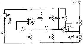
Schematic
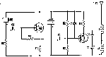
Click to Enlarge
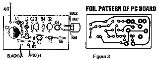
PCB Layout
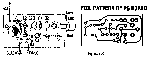
Click to Enlarge
|
|
Parts: |
C1 - .001uf Disc Cap
C2 - 5.6pf Disc Cap
C3,C4 - 10uf Electrolytic Cap
C5 - 3-18pf Adjustable Cap
R1 - 270 Ohm 1/8W Resistor
R2,R5,R6 - 4.7k 1/8W Resistor
R3 - 10k 1/8W Resistor
R4 - 100k 1/8W Resistor
Q1,Q2 - PNS2222A (or equlivelant) NPN Transistor
L1,L2 - 5 Turn Air Core Coil
MIC - Electret Microphone
MISC - 9V Battery Snap, PC Board, Wire For Antenna
|
| Notes on the Circuit: |
|
1. L1 and L2 are 5 turns of 28 AWG enamel coated magnet wire wound with a inside diameter of about 4mm. The inside of a ballpoint
pen works well (the plastic tube that holds the ink). Remove the form after winding then install the coil on the circuit board, being careful
not to bend it.
2. C5 is used for tuning. This transmitter operates on the normal broadcast frequencies (88-108MHz).
3. Q1 and Q2 can also be 2N3904 or something similar.
4. You can use 1/4 W resistors mounted vertically instead of 1/8 W resistors.
5. You may want to bypass the battery with a .01uf capacitor.
6. An antenna may not be required for operation.
|
|